Frequency Lowering
This document contains images and videos to aid in communicating the functionality of the system.
Section 1.0 Overview of Frequency Lowering - Navigation & Controls

Description:
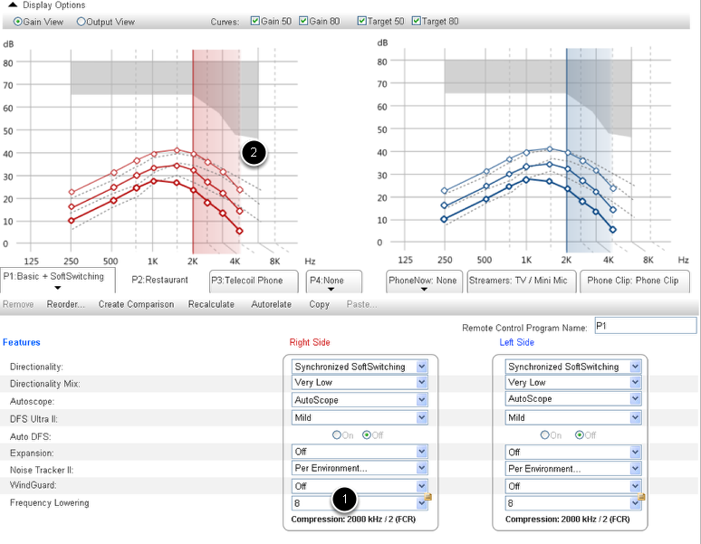
The Frequency Lowering (FL) feature can be located through the Advanced Feature setting (1). One control option proposed for the feature is a drop down menu (2) which has an initial setting of off and can be used to select FL values. When a frequency is selected and the feature is turned on, the FL feature will initiate a display of the frequency knee point on the graph (3) in real time as values are chosen. The save button (4) will save the settings.
Functional Requirements Met:
3.1.1.01 FSW shall provide a Frequency Lowering feature per program. The dispenser shall be able to turn on and off this feature and set its values.
3.1.1.03 It shall be possible to de-feature this feature and its values
3.1.1.06 The dispenser shall be able to turn off Frequency Lowering via FSW
Section 2.0 Frequency Lowering - Overview of Drop Down Menu Control
Description:
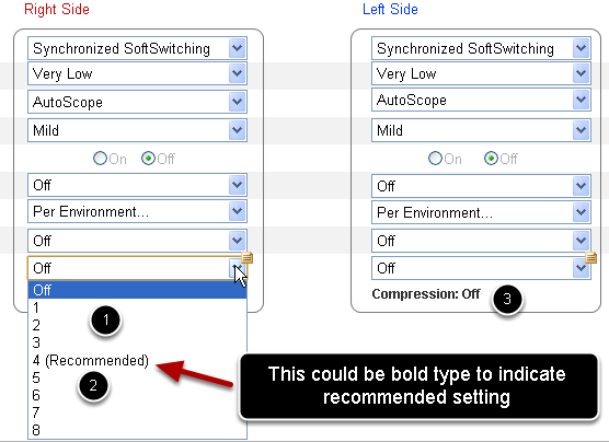
Selecting an FL value from the drop down menu (1) initiates the FL feature. A recommended setting (2) is highlighted in the menu through the use of bold type or "Recommended" in paranthesis beside the value. As a value is selected, the compression ratio displays under the menu (3). (See screencast demo below.)
Functional Requirements Met:
3.1.1.02 The Frequency Lowering feature shall have the following values:
FL Level rank number
1 (weakest) 5000 1.33
2 4000 1.33
3 4000 2
4 3500 2
5 3000 2
6 2500 2
7 2250 2
8 (strongest) 2000 2
3.1.1.05 Default values can be set per environment via product entry
3.1.1.08 FL shall support undo/redo functionality. This includes: (a) Turning the feature on or off; (b) Changing the FL level
Section 2.1 Screencast of Drop Down Menu Functionality
The above video provides an overview of the drop down menu changing the compression values and representing them.
Section 2.2 Drop Down Menu Controlling Graphical Representation of Frequency Lowering
Description:
Selecting a value on the FL drop down menu (1) manipulates the graph and illustrates the Frequency Lowering Knee Point visually (2). Graphical representation of FL values is covered in greater detail in Section 5.
Section 2.3 Screencast of Drop Down Menu Illustrating Graphical Representation of FL Value and Knee Point
Description:
This screencast illustrates the menu values being selected and subsequently represented in the graph.
Section 3.0 Slider Control Option Overview

Description:
A second option for the control of FL in the interface is a "slider" (1) to manipulate the FL values and turn the feature off. The slider has an initial setting of "off" - "off" is the far right position on the slider - just as the drop down menu does. The off setting (or current FL setting) is indicated in two ways - the number on the slider knob (zero is an "off" setting) and an "Off" value in the compression ratio window/indicator under the slider (2). The number on the slider changes and the compression ratios in the window change as the slider is drug along the X axis (see screencast below for detail). The slider operates in the same manner as the Mic / Mini Mic feature under "Advanced Settings" in the Aventa fitting software. That is, there is no granularity, each tic mark on the slider bar represents a value and there is no value in between tic marks. The recommended value (based on the audiogram of the patient) is represented through the use of a bold tic mark (3). The graph also changes as the slider is adjusted to display the FL values and knee point.
Functional Requirements Met:
3.1.1.01 FSW shall provide a Frequency Lowering feature per program. The dispenser shall be able to turn on and off this feature and set its values.
3.1.1.02 The Frequency Lowering feature shall have the following values:
FL Level rank number
1 (weakest) 5000 1.33
2 4000 1.33
3 4000 2
4 3500 2
5 3000 2
6 2500 2
7 2250 2
8 (strongest) 2000 2
3.1.1.03 It shall be possible to de-feature this feature and its values
3.1.1.05 Default values can be set per environment via product entry
3.1.1.06 The dispenser shall be able to turn off Frequency Lowering via FSW
3.1.1.08 FL shall support undo/redo functionality. This includes: (a) Turning the feature on or off; (b) Changing the FL level
Section 3.1 Screencast of Slider Function
The above screencast illustrates the slider functionality and the graphical manipulation of the FL through the use of the slider.
Section 4.0 Setting FL Value Globally
Description:
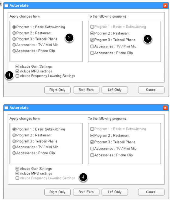
Setting the FL value in more than one program can be facilitated through the use of the Autorelate feature. This chaanges the interface for Autorelate by including the Gains Settings as a checkbox and adding an FL checkbox (1). The prgrams to move from (2) can be selected as well as the program to move the settings to (3). If the autorelate button is selected and FL is not set or tunred on as a feature, the ckeckbox will appear greyed out (4). The screencast below illustrates this feature in real time.
Functional Requirements Met:
3.1.1.07 Although this feature is per program, it shall be possible to turn this feature on and set the feature value for all programs at the same time
Section 4.1 Screencast of Autorelate Functionality
This screencast illustrates the Autorelate feature with FL added as an option.
Section 5.0 Graphical Representation of FL
Description:
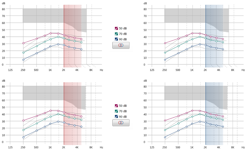
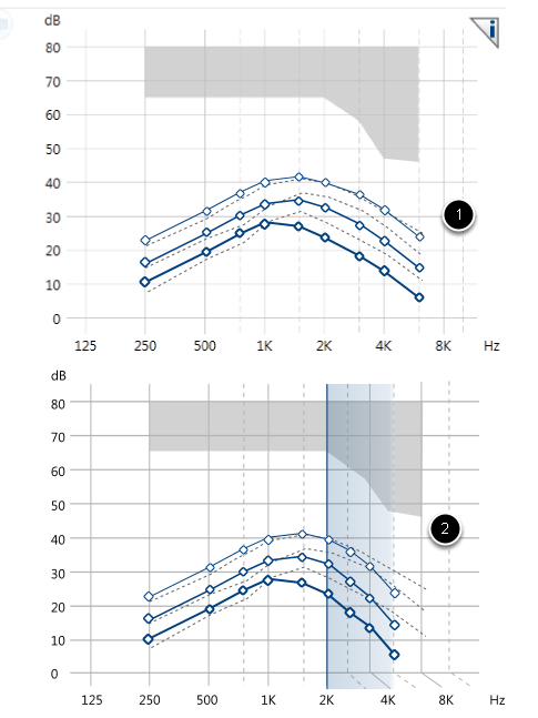
The graphical represntation of the FL value and knee point is shown in the images above. The normal view (1) acts as the initial setting when the FL feature is off. As the FL value is manipulated using the control, the compression is represented (2) with the levels being compressed into a different frequency. Note the Hz lines shifting along the graph in the second graph above.
Functional Requirements Met:
3.1.2.02 (Part A, B & D) The gain and output charts will show the effects of FL when the feature is on. A) The FCKP should be indicated; B) The responses should show the frequencies being compressed; D) Changing the Level may affect the responses. Any effects shall be shown in the FSW gain grid, gain chart and output chart
Section 5.1 Two Options for Grahical Representation
Description:
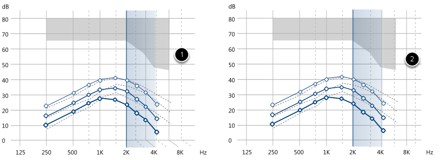
In the first graph (1), note the Hz lines shift as the FL shifts to lower frequencies. In the second graph (2), the lines stay in place and only the curves shift to lower frequencies. These are two options for graphically representing the FL shifiting.
Section 5.2 Graphically Representing Output
Description:
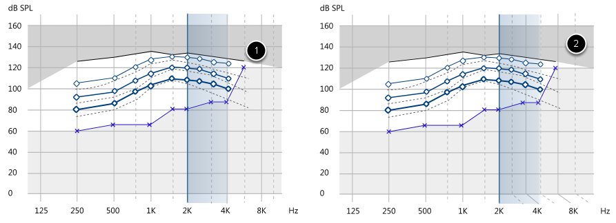
The output view for FL is displayed above and can be accessed through selecting the Output View under Display Options above the graph.There are two options. The first (1) has Hz lines that do not shift and the second has lines that shift (2).
Section 5.4 Representing Compression Value with Rollovers
Description:
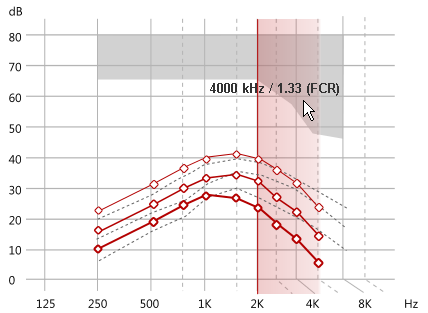
The graphs will each display the compression ratio iusing rollovers ("or mouseovers") when an FL value is set.
Section 6.0 Dispenser Print Report
Description:
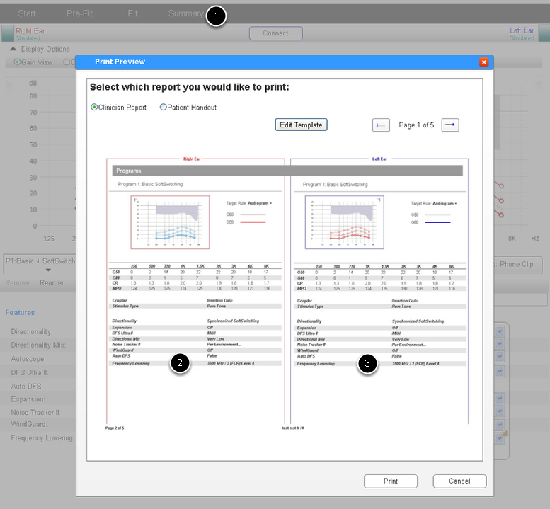
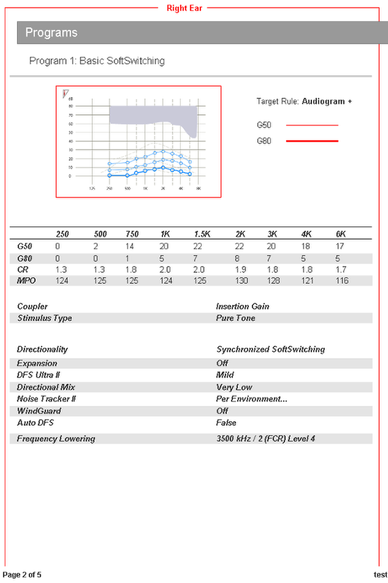
The dispenser print report will have a line indicating the FL settings for the patient (2 & 3). This feature can be accessed by selecting Summary (1) from top navigation.
Functional Requirements Met:
3.1.3.01 The settings for FL shall be shown in the dispenser print reports
3.1.3.02 The effect of FL on responses shall be shown in the dispenser print report
Section 6.1 Screencast of Dispenser Print Report Feature
Description:
This screencast illustrates the dispenser print report feature in real time.
Section 6.2 Enlarged View of Dispenser Print Report
Description:
The above image serves as a detailed view of the Dispenser Print Report
Appendix A: Recommended Default Values
The displayed values are recommendations we may wish to consider. These are only recommendations and not guidelines.
Appendix B: Graphs with Shifting Hz Lines and without (Option 1 & 2)
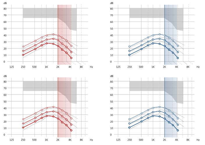
These images are for reference and comparison. They show options for displaying graphs of FL values with Hz lines shifting and without Hz lines shifting.
Appendix C: Graph Outputs (Options 1 & 2)

These images are for reference and comparison. They show options for displaying output with Hz lines shifting and without Hz lines shifting.